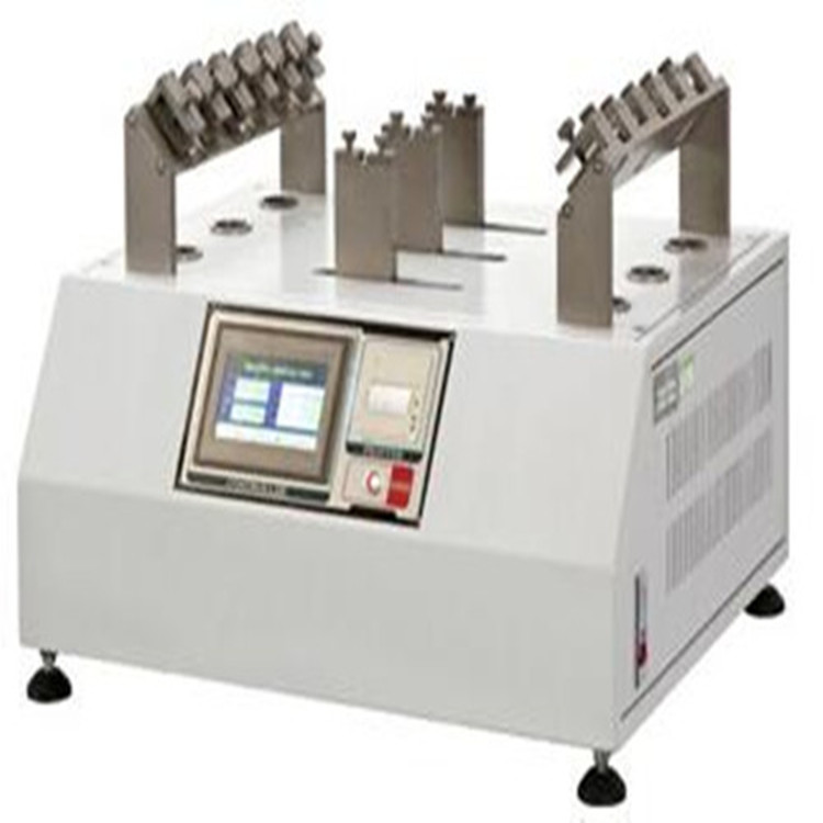
The core structure of the shoelace and shoe hole wear tester
The wear resistance of shoelaces and shoe eyelets is a key indicator of footwear durability. The core structure of a wear tester, which accurately measures this performance, can be described as a "micro-tribological laboratory." From the drive system that simulates real-world wear scenarios to the detection module that accurately captures wear data, each component carries the crucial mission of quantifying durability.
Drive System: The Power Core for Replicating Realistic Wear
The drive system is the heart of the tester, its core function being to simulate the dynamic friction between shoelaces and shoe eyelets during human walking. Modern testers often utilize a dual-axis drive design: the horizontal axis controls the reciprocating friction frequency of the shoelaces, precisely matching different exercise intensities such as walking, brisk walking, and running; the vertical axis, through a servo motor, applies variable tension, simulating the pressure changes during shoelace lacing. This allows for a wide range of scenarios, from the gentle tightening of children's shoes to the firm hold of hiking boots.
To replicate real-world usage, the drive system also features environmental simulation components. In high-temperature testing mode, the heating module stabilizes the temperature around the shoe eyelets at 35-40°C, simulating the hot and humid environment of sweaty feet. In low-temperature mode, it can be lowered to -10°C to test the wear resistance of winter footwear in cold, dry conditions. This "dynamic + environmental" hybrid drive design keeps the deviation between laboratory test data and actual wear experience within 5%.
Simulated Friction Mechanism: Accurately Replicating Contact Form
The friction mechanism is the "execution terminal" of the testing machine, and its design directly determines the authenticity of the test. The shoe eyelet fixing device adopts a modular design, compatible with various shoe eyelet shapes such as round, oval, and square. A magnetic quick-change mechanism allows switching from canvas shoe eyelets to leather shoe metal eyelets in just 30 seconds. More crucial is the shoe eyelet angle adjustment function – a rotating axis allows for 0-30° tilt adjustment, perfectly replicating the tilted friction between the shoelace and the shoe eyelet when the foot is bent.
The shoelace clamping system is a hidden detail with ingenious design. Specially designed silicone clamps securely secure the ends of the shoelaces while preventing additional wear at the clamping point. The universal joint structure connecting the clamps automatically adjusts its angle during the friction process, ensuring the shoelaces maintain a natural contact with the eyelet. When testing high-strength outdoor shoelaces, the mechanism also activates an "accelerated wear" mode. By adding micro-bumps to the friction path, this simulates localized stress concentration between the shoelaces and the eyelet edges, shortening the test cycle while maintaining data accuracy.
Wear Detection Module: Capturing Micron-Level Changes
Wear detection is the "intelligent brain" of the testing machine, and its accuracy directly determines the reliability of the test results. The optical detection unit utilizes a high-resolution industrial camera, coupled with a 45° tilted light source, to capture microscopic changes in the shoelace surface in real time during friction. Image recognition technology is used to calculate the wear area with a minimum accuracy of 0.01 square millimeter. For eyelet wear detection, a laser profilometer scans the eyelet edge every 100 friction cycles, generating a 3D profile. Comparing this profile with the initial state allows accurate wear depth determination down to the micron level.
The weight loss detection module provides supplementary verification by regularly measuring shoelace weight changes using a high-precision electronic balance (accuracy 0.1 mg). When fiber loss occurs due to shoelace wear, the weight loss data is cross-validated with the wear area detected by optical inspection, eliminating errors associated with a single detection method. After the test, the system automatically generates a "wear volume - friction number" curve, visually displaying the wear rate changes at different stages, providing accurate data support for material improvement.
Control System: Achieving Full-Process Intelligence
The control system is the "nerve center" of the testing machine, integrating parameter setting, process monitoring, and data processing. On the 10.1-inch touchscreen, operators can access 20 pre-set standard test procedures covering mainstream footwear standards such as ISO, ASTM, and GB. Operators can also customize 12 parameters, including friction number, tension, and ambient temperature, to generate customized test plans and save them to the cloud.
Especially noteworthy is the intelligent warning function. If the system detects abnormal shoelace breakage or excessive shoe hole deformation, it automatically pauses the test and triggers an audible and visual alarm. It also saves the current data point to avoid wasted testing. The built-in data analysis module automatically calculates the wear resistance rating—classifying shoes into five grades based on the number of frictions required to reach a wear threshold. The rating report includes wear images and data curves, transforming the abstract concept of "durability" into a concrete, quantitative indicator.
From the dynamic simulation of the drive system to the micron-level capture of the detection module, the core structure of the shoelace and eyelet wear tester is designed with the goal of "realistic reproduction and precise quantification." The coordinated operation of these precision components not only provides shoe companies with a scientific basis for product improvement, but also ensures that every pair of shoes in consumers' hands has undergone thousands of laboratory-level "durability tests."